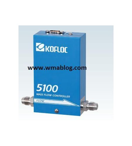
MODEL 5100 SERIES
Features
-High accuracy and high response are achieved by the flow sen-sor with temperature- following current difference detection.
-A normally-closed solenoid valve is employed.
-A low leak rate is achieved by the weldless structure and metalseal.
-The dead volume is reduced thanks to the diaphragm seat valve.
-The face-to-face and body dimensions and the wiring tie-inpoints are designed to facilitate replacement of devices made by other companies.
Standard Spesifications
|
Flow range (N2 equivalent, |
1 SCCM–20 SLM (The conditions are freely selectable) |
|
Sensor |
Thermal mass flow sensor |
|
Valve type |
Proportional solenoid valve (closed when not energized) |
|
Control range |
2–100% (F.S.) |
|
Response |
1 sec. or less (0–100% within ±2% typical) |
|
Accuracy |
±1% F.S. (Accuracy guaranteed at 15–35℃) |
|
Repeatability |
±0.2%F.S. |
|
Operating differential |
F.S. ≤ 5 SLM: 50–300 kPa |
|
F.S. > 5 SLM: 100–300 kPa |
|
|
Option: Low differential pressure (LP) specification is available depending on conditions. |
|
|
Allowable operating pressure |
300 kPa (G) or less |
|
Proof pressure |
980 kPa (G) |
|
Leak rate |
1 × 10-11 Pa·m3/s or less |
|
Allowable ambient temperature |
0–50℃ |
|
Allowable ambient humidity |
10–90% (No condensation allowed) |
|
Materials of parts in |
Body: SUS316L |
|
Diaphragm:SUS316L |
|
|
Valve seat: PTFE |
|
|
Sealing: SUS316L, Ni, Au |
|
|
Option: SUS seal (SU), inner surface polish (KP) |
|
|
Electric connection |
Dsub 9-pin connector as per KFC Standard (Compliant with SEMI Standard) |
|
Flow rate input signals |
0–5 VDC (Input impedance: 1 MΩ or more) |
|
Flow rate output signals |
0–5 VDC (External load resistance: 250 kΩ or more) |
|
Required power supply |
+15 VDC (±5%) 100 mA, −15 VDC (±5%) 200 mA |
|
Joint (Main unit bore) |
Standard: 1/4 VCR equivalent Option: 1/4 SWL |
|
Weight |
Approx. 1000 g |
Harness Layout
Pin Assigment of Dsub 9-pin Connector per KFC Standard
|
Pin No |
Signal |
Pin No. |
Signal |
|
1 |
Input valve open/close operation |
6 |
Flow input Hi |
|
2 |
Flow output 0-5 V |
7 |
Flow output COM |
|
3 |
+15 VDC power source |
8 |
Flow input Lo |
|
4 |
Power source COM |
9 |
Output valve voltage |
|
5 |
-15 VDC power source |
|
|
Because a differential input system in used for the product, pin 4 (power source COM) and pin 7 (flow outpum COM) are connected inside the mass flow controller while pin 8 (flow input Lo) is isolated. In case of a single-ended connection , connect pin 8 to pin 4


