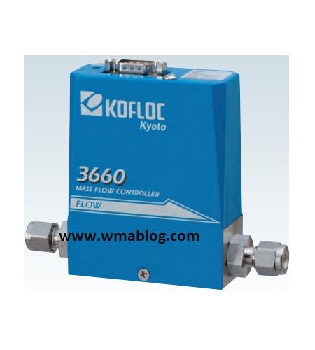
MODEL 3660 SERIES
Model 3660 Series Mass Flow Controller has been developed centerign the focus on compactness and low cost and is being acclaimed by a wide range of users for diverse appllications, including from laboratory research and devolopment activities to the use as standartd mass flow control model for various types odf analyzers and vacuum devices in the production line. Varieties of derived models and options are avaible.
Features
· - Equipped with an advancesd flow sensor of constant-current temperature difference detection type tu ensure high-speed response
· -Use of a normally closed valve to ensure safety
· -High reliabillity ensured using a selenoid actuar
· -Low differential pressure type control avaible for combustible gases (LP option)
Standard Specifications
|
Model |
3660 |
3665 |
|
Flow range (N2 equivalent, |
10 SCCM–20 SLM (freely |
30 SLM–100 SLM (freely |
|
Sensor |
Thermal mass flow sensor |
|
|
Valve type |
Proportional solenoid valve (closed when not energized) |
|
|
Control range |
2–100% (F.S.) |
5–100% (F.S.) |
|
Response |
2 sec. or less (0–100% within |
3 sec. or less (0–100% within |
|
Accuracy |
±1.0% F.S. (25℃) |
±1.5% F.S. (25℃) |
|
Temperature coefficient |
±0.1 F.S./℃ (15–35℃) |
±0.2 F.S./℃ (15–35℃) |
|
Repeatability |
±0.5%F.S. |
|
|
Operating differential pressure |
F.S. ≤ 5 SLM: 50–300 kPa (G) |
F.S. ≤ 50 SLM: 150–300 kPa (G) |
|
F.S. > 100 SLM: 50–300 kPa (G) |
F.S. > 50 SLM: 200–300 kPa (G) |
|
|
Option: Medium differential pressure (MP) and low differential pressure (LP) specifications are available. |
||
|
Allowable operating pressure |
500 kPa (G) or less |
|
|
Proof pressure |
980 kPa (G) |
|
|
Leak rate |
1 × 10⁻⁸ Pa.m3/s or less (excluding permeation of He) |
|
|
Allowable ambient temperature |
5–45°C |
|
|
Allowable ambient humidity |
10–90% (No condensation allowed) |
|
|
Materials of parts in contact with gases |
Body: SUS316 |
|
|
Valve seat: FKM (option: CR or NBR) |
||
|
Sealing: FKM (option: CR or NBR) |
||
|
Electric connection |
Dsub 9-pin connector as per KFC Standard (Compliant with SEMI Standard) |
|
|
Flow rate input signals |
0–5 VDC (Input impedance: 1 MΩ or more) |
|
|
Flow rate output signals |
0–5 VDC (External load resistance: 250 kΩ or more) |
|
|
Required power supply |
+15 VDC (±5%) 100 mA, −15 VDC (±5%) 250 mA |
|
|
Joint (Main unit bore) |
Standard: 1/4SWL |
Standard: 3/8SWL |
|
Weight |
Approx. 1000 g |
Approx. 1500 g |
Harness Layout
|
Pin No |
Signal |
Pin No. |
Signal |
|
1 |
Input valve open/close operation |
6 |
Flow input Hi |
|
2 |
Flow output 0-5 V |
7 |
Flow output COM |
|
3 |
+15 VDC power source |
8 |
Flow input Lo |
|
4 |
Power source COM |
9 |
Output valve voltage |
|
5 |
|
|
|
· Because a differential input system in used for the product, pin 4 (power source COM) and pin 7 (flow outpum COM) are connected inside the mass flow controller while pin 8 (flow input Lo) is isolated. In case of a single-ended connection , connect pin 8 to pin 4


